Video Intercom/SIP 2.0/Stand Alone Multiple VTH and VTO Setup
| Icon | Name | Generation | Technology | SIP 2.0 | Example Device 1 | Example Device 2 | Identifying Characteristic | PC Software | Mobile App |
|---|---|---|---|---|---|---|---|---|---|
| Gen2-SIP2.0-IP | Gen 2 | IP | SIP 2.0 | VTH1550CH-S | DHI-VTO2000A-S | "-S" at end of model name | DSS or DSS Express S | DSS Mobile for VDP |
Contents
Stand Alone Multiple VTH and VTO Setup
Description
This guide will show how to setup multiple VTO and VTH devices on a network
In this example a VTO will be designated as the main VTO and also act as the SIP server for the installation
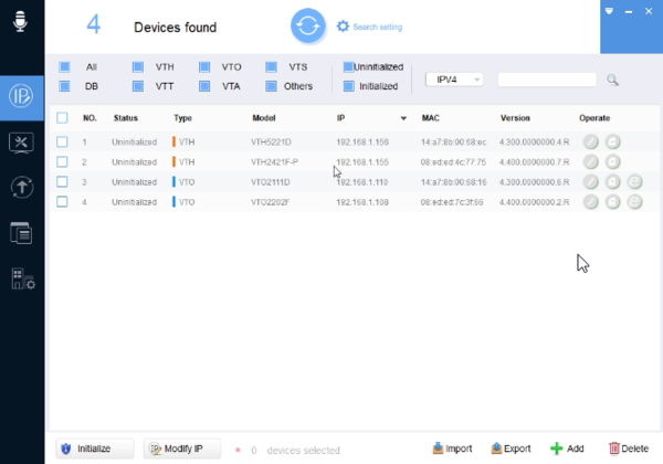
In this example a VTO2202F-P will act as Main VTO and a VTO2111D will act as Sub VTO. The VTH2421FW-P will act as the Main VTH and will send the SIP/VTO information to our extension VTH5221D-S
Prerequisites
- Laptop/PC on the same network
- VDP Config
- Gen2 SIP VTOs and VTHs
Devices
NOTE: These are the device settings we used for this article
Video Instructions
Step by Step Instructions
Main VTO Setup (SIP Server)
1. Find the VTO you would like to make the Main
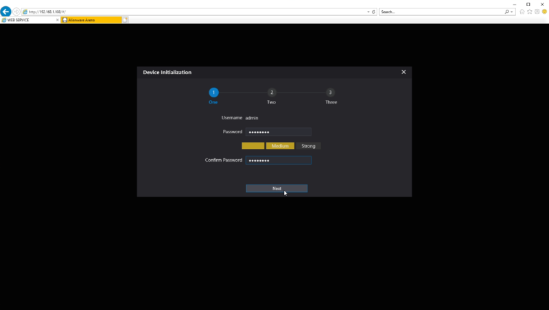
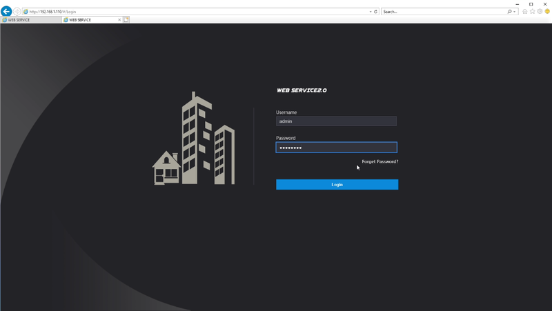
2. Type the IP Address on a browser and setup a password for the VTO. In this tutorial we used admin123
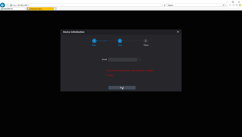
3. Please enter an email in case you lose the admin password
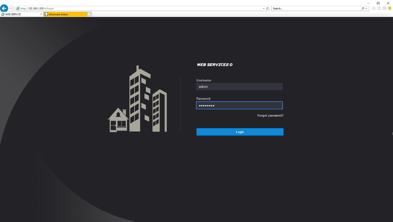
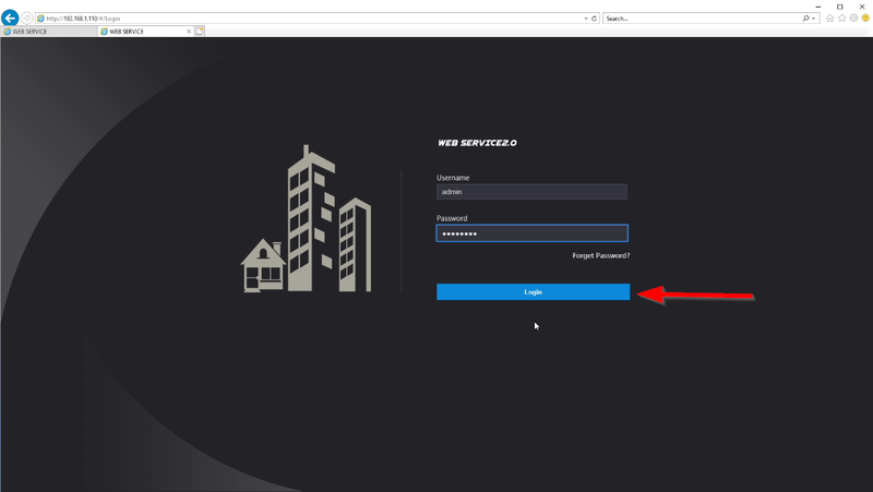
4. Login to the WEBUI using the password you just created
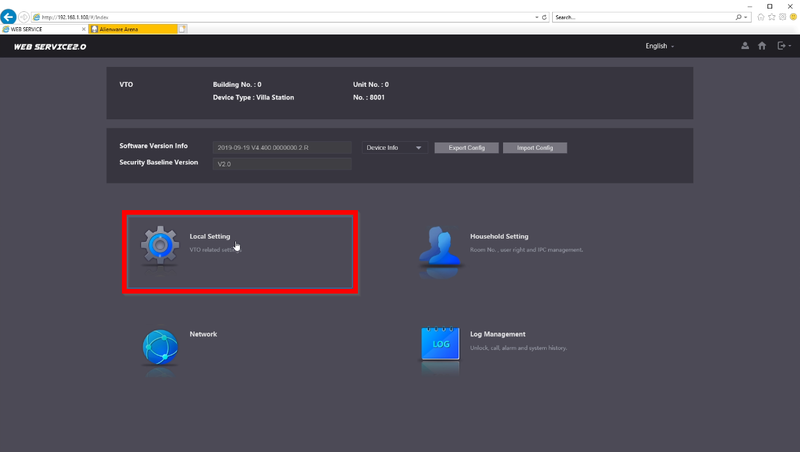
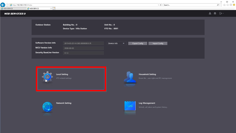
5. First step is to go to "Local Setting"
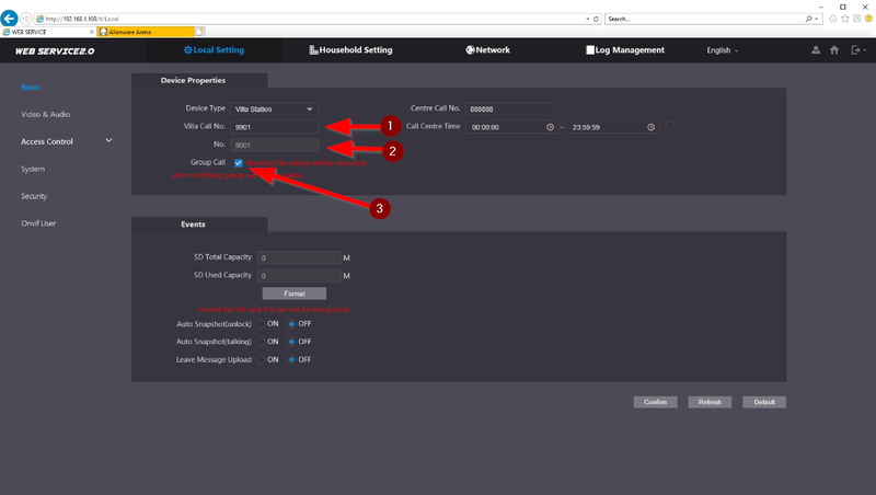
6. Review the settings and make sure Group Call is enabled
Villa Call No. : This indicates the Room No on the VTH it will reach out too
No. : No. is the VTO Number. It can be changed when SIP server is disabled
Group Call: This will call all VTHs on the same Room No family including Extensions
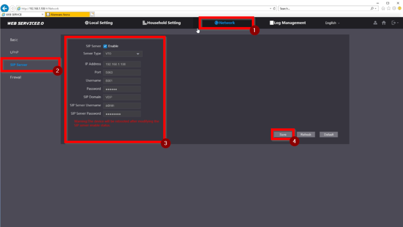
7. Navigate to over to Network -> SIP Server (You will need to Disable the SIP Server in order to make changes)
SIP Server: Enabled
Server Type: VTO
IP Address: 192.168.1.108 (Master VTO)
Port: 5060
Username: 8001
Password: (Leave default)
SIP Domain: VDP
SIP Server Username: admin
SIP Server Password: admin123
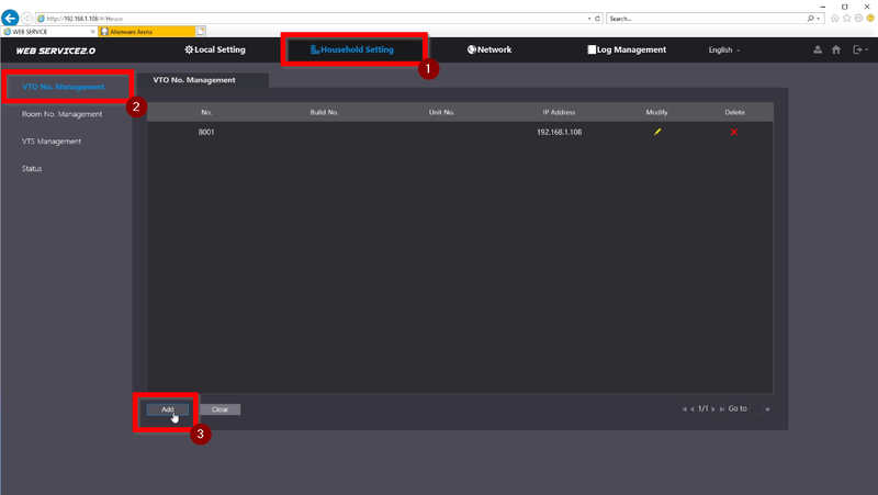
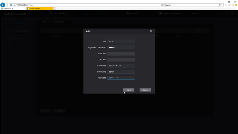
8. Navigate over to VTO No. Management and click on "Add" to add the SUB VTO we will be adding later
9. Enter the info and credentials of the SUB VTO we will be using
No.: 8002
Registered Password: (Leave default)
Build No.: (Leave default)
Unit No.: (Leave default)
IP Address: 192.168.1.110
Username: admin
Password: admin123
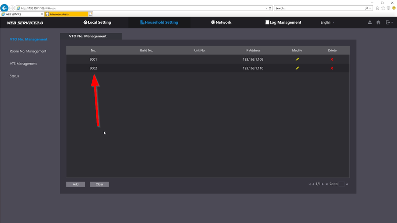
10. Once added you will see the entry in the list.
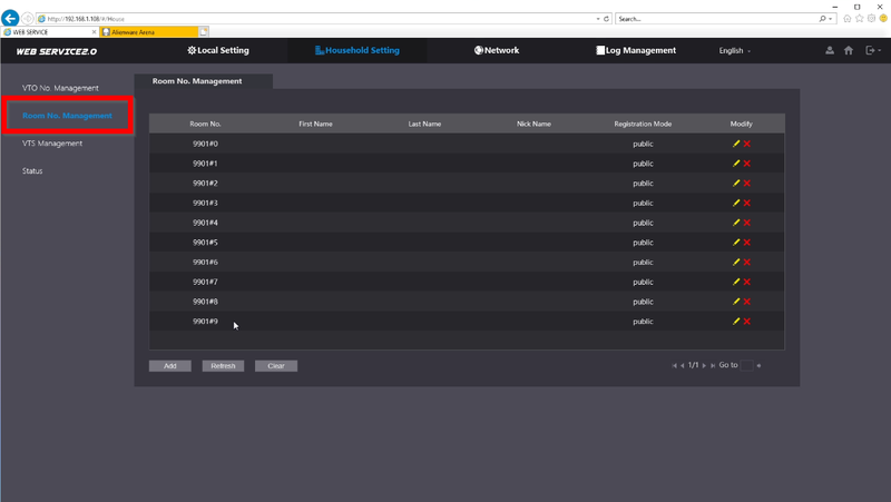
11. The VTHs should already be added by default.
If not please add the Master VTH 9901#0 and any other extensions needed by adding #1, #2, etc..
SUB VTO Setup
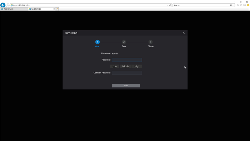
1. Use the IP Address of the SUB VTO to login to the WEBUI. Go through the Initialization phase.
2. Login with the password we just created. In this tutorial we used admin123
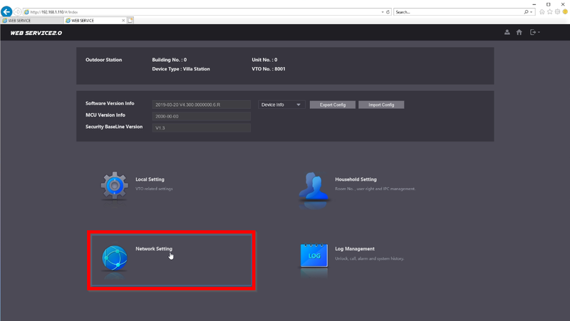
3. Go to "Network Settings"
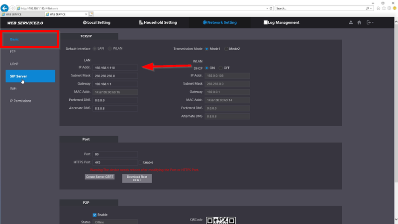
4. We will be using 192.168.1.110 for the SUB VTO
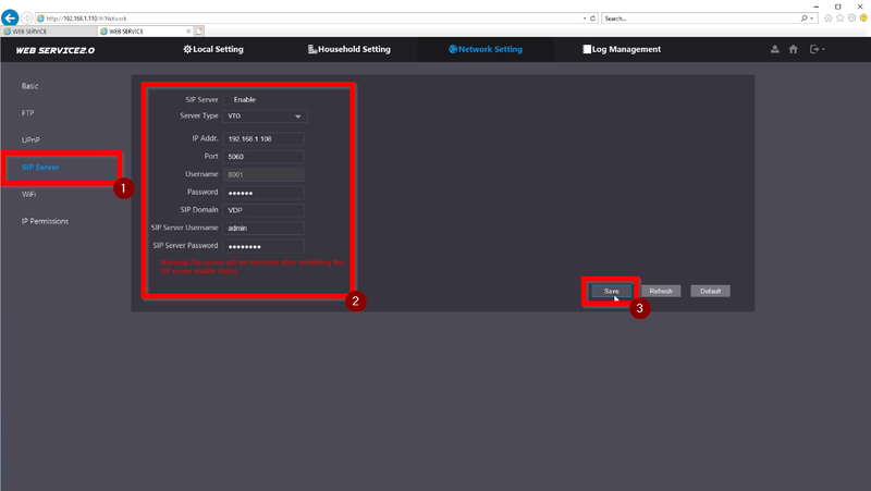
5. Go to SIP Server and enter the SIP Server Information. The device will reboot after saving the settings.
SIP Server: Disabled
Server Type: VTO
IP Address: 192.168.1.108
Port: 5060
Username:8002 (this will not be changeable until the device reboots)
Password: (Leave Default)
SIP Domain: VDP
SIP Server Username: admin
SIP Server Password: admin123
6. Login after the reboot
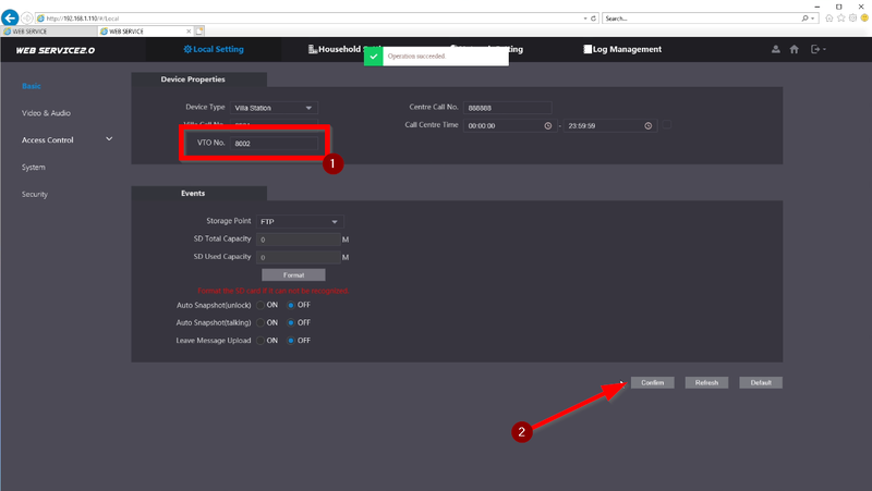
7. Go to Local Settings
8. Change the VTO No. to 8002 and click on "Confirm" to save
Main VTH Setup
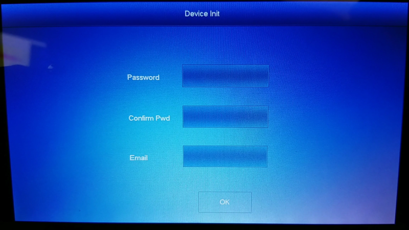
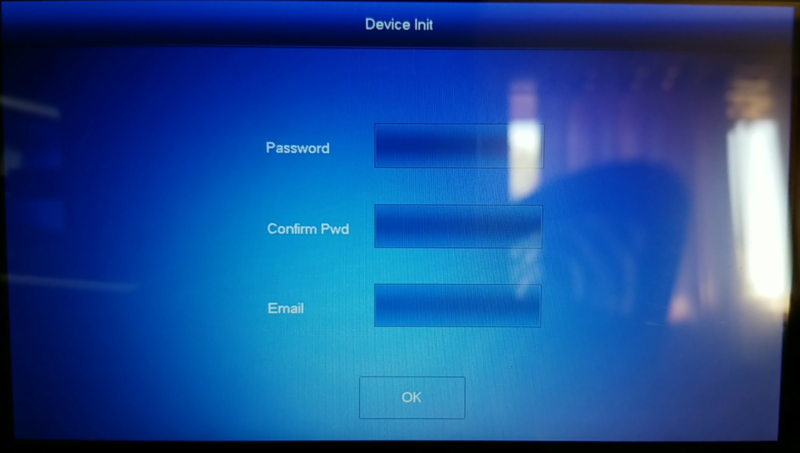
1. Initialize the VTH with a password and email. In this tutorial we used 123456
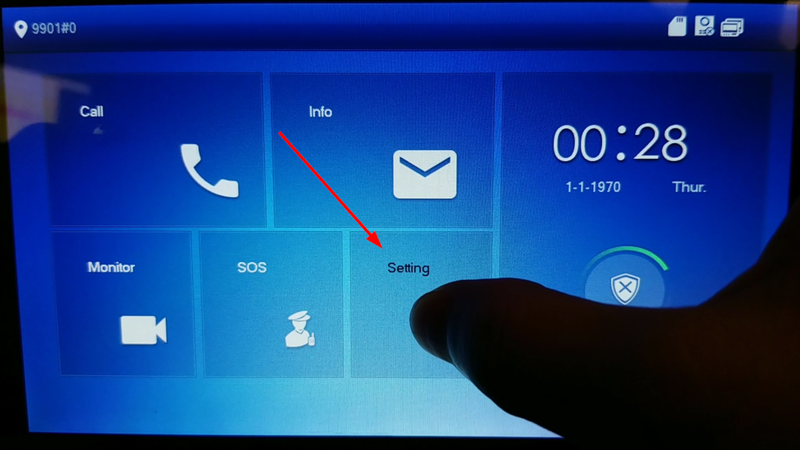
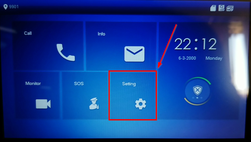
2. Tap and hold the settings icon to enter the Configuration settings and use the password you initialized the VTH with
Note: a single tap will enter the general settings so be sure to tap and hold until the login prompt comes up. General Settings uses default password "123456"
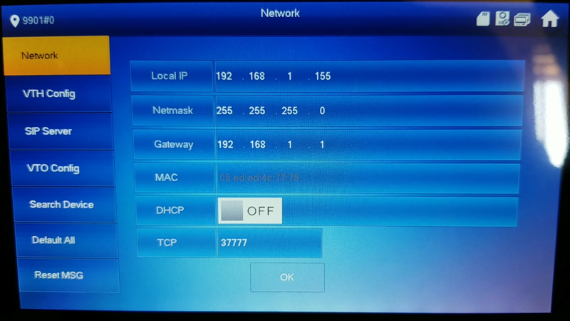
3. We will be using IP Address 192.168.1.155 for the Master VTH
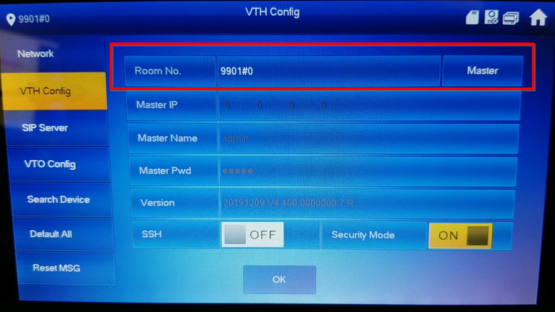
4. Go to VTH Config and confirm that the Room No. is 9901#0 with the label as "Master"
The #0 indicates that its the master. #1 will be the first following Extension followed by #2, #3, etc..
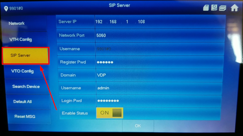
5. Go to SIP Server and enter the SIP Server information
Server IP:192.168.1.108
Network Port: 5060
Username: 9901#0
Register Pwd: (Leave Default)
Domain:VDP
Username: admin
Password: admin123
Status: ON
6. No we need to add the VTOs to be able to Monitor through the VTH's Home Screen.
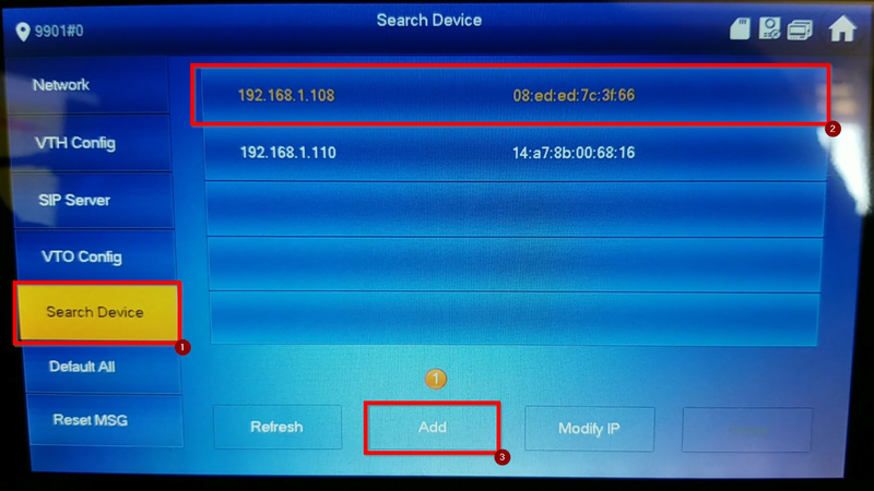
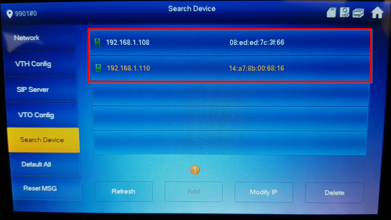
Highlight the Main VTO and tap on "Add"
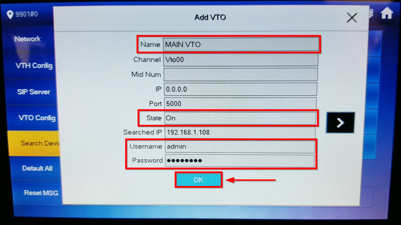
7. Enter only the highlighted sections
Name: (Nickname so enter any name to identify the Master VTO)
State: ON
Username: admin (VTO username)
Password: admin123 (VTO Password)
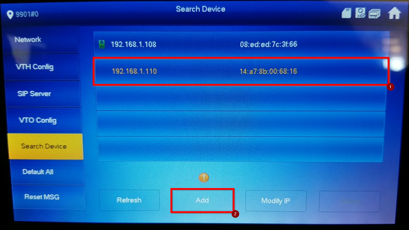
8. A green icon will appear next to the VTO added. Now Tap and highlight the Sub VTO and click on "Add"
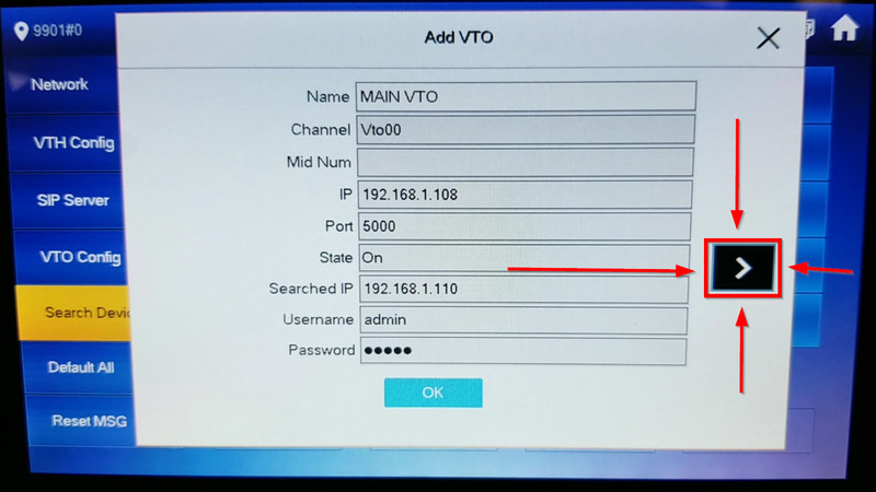
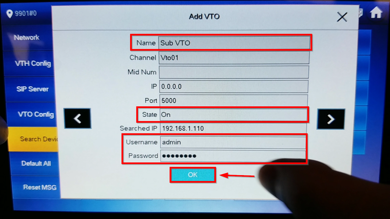
9. The same prompt will appear but don't override the Main Entry, click on the arrow to go to the second entry.
10. Change only the highlighted sections
Name: (Nickname to identify the SUB VTO)
State: ON
Username: admin (SUB VTO username)
Password: admin123 (SUB VTO Password)
11. Both devices will show a green icon after being added.
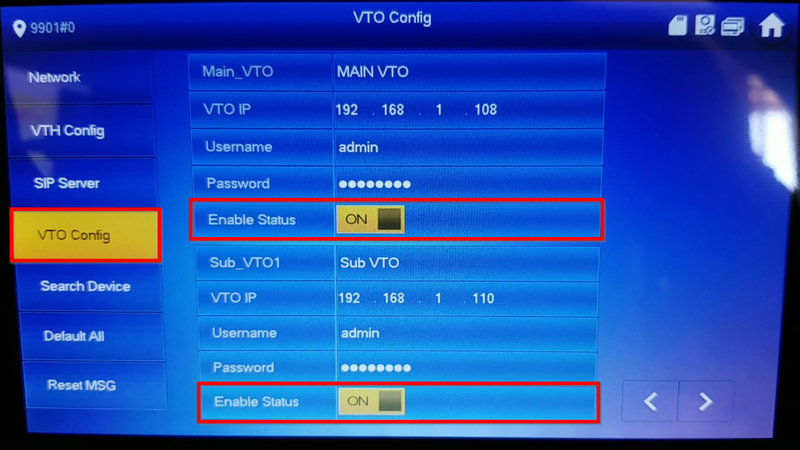
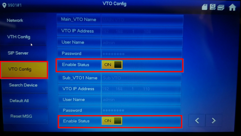
12. Go to "VTO Config" and confirm that the status on all added VTOs are enabled.
Sub VTO Setup
The Extension VTH will grab the information from the Master VTH if configured properly
1. Initialize the SUB VTO that will be acting as the first Extension
2. Enter the Configuration Settings by taping and holding the settings icon
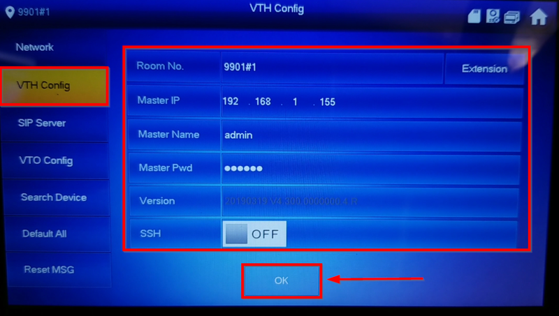
3. Go to VTH Config and change the label to "Extension". Be sure to change the Room No to the first extension by adding #1 after 9901. Click OK to Save
Room No.:9901#1
Master IP: 192.168.1.155 (Enter the IP Address of the Main VTH)
Master Name: admin (username of the Main VTH)
Master Pwd: 123456 (Password of the Main VTH)
4. If Step 3 was successful you should see the entries of the VTOs. Be sure to enable them
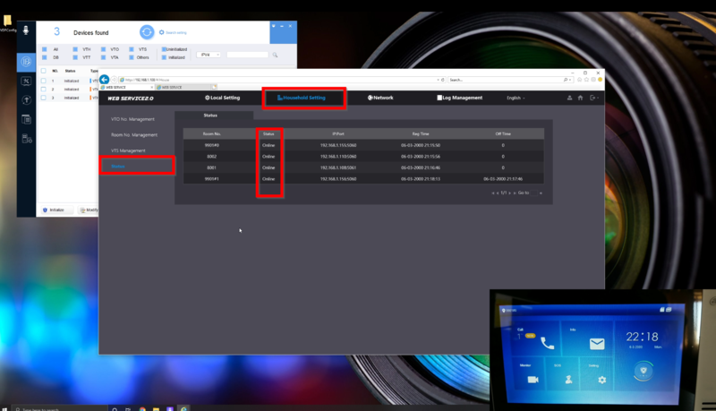
5. All devices should be online and ready to call.


