NVR/Alarm Panel
Revision as of 19:40, 26 October 2015 by JP (talk | contribs) (Created page with "==Alarm COnnection== ===Alarm Port=== The alarm port is shown as below. The following figure is based on the 78 series. file:NVRAlarmDiagram1.png {| class="wikitable" wi...")
Alarm COnnection
Alarm Port
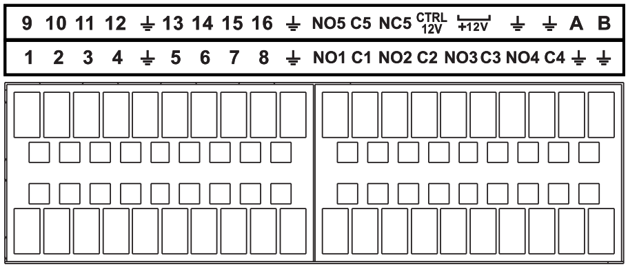
The alarm port is shown as below. The following figure is based on the 78 series.
|
Icon |
Function |
|
1~16 |
ALARM1~ALARM16. The alarm becomes activated in the low level. |
|
NO1 C1,NO2 C2,NO3 C3,NO4 C4 |
Four NO activation output groups. (On-off button). |
|
NO5 C5 NC5 |
One NO/NC activation output group. (On-off button). |
|
CTRL 12V |
Control power output. Disable power output when alarm is canceled. Current is 500mA. |
|
+12V |
Rated current output. Current is 500mA. |
|
GND | |
|
A/B |
485 communication port. They are used to control devices such as PTZ. Please parallel connect 120TΩ between A/B cables if there are too many PTZ decoders. |
