Thermal/DHI-ASI7213X-T1/Instructions/Alarm Input and Output
Revision as of 19:11, 11 August 2020 by AlexS (talk | contribs) (→Normal Body Temperature Indication Light)
Contents
- 1 Alarm Input and Output
- 1.1 Web Interface
- 1.2 Cable Connections
- 1.3 Normal Body Temperature Indication Light
- 1.4 High Body Temperature Indication Light
- 1.5 Door Strike Physical Setup
- 1.6 Door Release Button Physical Setup
- 1.7 Card Reader:RS485
- 1.8 Card Reader:Wiegand
- 1.9 WebUI Alarm Setup
- 1.10 SystemUI Set Temperature Threshold
Alarm Input and Output


Web Interface
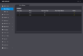
Alarm Linkage
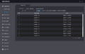
Alarm Linkage Log
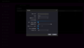
Alarm Linkage-Modify


Cable Connections
- Alarm1 = High Temp
- Alarm2 = No Mask
- No alert for face detection currently.
Contact 1
| Port | Cable Color | Cable Name | Description | |
|---|---|---|---|---|
| CON1 | ||||
| Black | 35px | RD– | Negative electrode of external card reader. | |
| Red | 35px | RD+ | Positive electrode of external card reader. | |
| Blue | 35px | CASE | Tamper alarm input of the external card reader. | |
| White | 35px | D1 | Wiegand D1 input (connected to external card reader)/output (connected to controller). | |
| Green | 35px | D0 | Wiegand D0 input (connected to external card reader)/output (connected to controller). | |
| Brown | 35px | LED | Connected to external reader indicator in | |
| Yellow | 35px | B | RS-485 negative electrode input (connected to external card reader)/output (connected to controller, or connected to door control security module).
| |
| Purple | A | RS-485 positive electrode input (connected to external card reader)/output (connected to controller, or connected to door control security module).
| ||
Contact 2
| Port | Cable Color | Cable Name | Description | |
|---|---|---|---|---|
| CON2 | ||||
| White and red | 35px | ALARM1_NO | Alarm 1 normally open output port | |
| White and orange | 35px | ALARM1_COM | Alarm 1 common output port. | |
| White and blue | 35px | ALARM2_NO | Alarm 2 normally open output port. | |
| White and gray | 35px | ALARM2_COM | Alarm 2 common output port. | |
| White and green | 35px | GND | Connected to the common GND port. | |
| White Brown | 35px | ALARM1 | Alarm 1 input port. | |
| White and yellow | 35px | GND | Connected to the common GND port. | |
| White and purple | ALARM2 | Alarm 2 input port. | ||
Contact 3
| Port | Cable Color | Cable Name | Description | |
|---|---|---|---|---|
| CON3 | ||||
| Black and blue | 35px | GND | Connected to the common GND port. | |
| Black and gray | 35px | SR1 | Used for door contact detection. | |
| Black and green | 35px | PUSH1 | Door open button of door No.1 | |
| Black and brown | 35px | DOOR1_COM | Lock control common port. | |
| Black and yellow | 35px | DOOR1_NO | Lock control normally open port. | |
| Black and purple | DOOR1_NC | Lock control normally closed port. | ||
Normal Body Temperature Indication Light
| PLEASE NOTE: With firmware version 1.000.10BE001.0.R.200722, Normal Body Temperature Alarm Output must be wired to DOOR1_NC and DOOR1_COM instead of ALARM1_NO and ALARM1_COM in the below diagram |
|---|

| Port | Cable Color | Cable Name | Description | |
|---|---|---|---|---|
| CON2 | ||||
| White and red | 35px | ALARM1_NO | Alarm 1 normally open output port | |
| White and orange | 35px | ALARM1_COM | Alarm 1 common output port. | |
High Body Temperature Indication Light

| Port | Cable Color | Cable Name | Description | |
|---|---|---|---|---|
| CON2 | ||||
| White and blue | 35px | ALARM2_NO | Alarm 2 normally open output port. | |
| White and gray | 35px | ALARM2_COM | Alarm 2 common output port. | |
Door Strike Physical Setup

| Port | Cable Color | Cable Name | Description | |
|---|---|---|---|---|
| CON3 | ||||
| Black and brown | 35px | DOOR1_COM | Lock control common port. | |
| Black and purple | DOOR1_NC | Lock control normally closed port. | ||
Door Release Button Physical Setup

| Port | Cable Color | Cable Name | Description | |
|---|---|---|---|---|
| CON3 | ||||
| Black and blue | 35px | GND | Connected to the common GND port. | |
| Black and green | 35px | PUSH1 | Door open button of door No.1 | |
Card Reader:RS485
| Port | Cable Color | Cable Name | Description | |
|---|---|---|---|---|
| CON1 | ||||
| Yellow | 35px | B | RS-485 negative electrode input (connected to external card reader)/output (connected to controller, or connected to door control security module).
| |
| Purple | A | RS-485 positive electrode input (connected to external card reader)/output (connected to controller, or connected to door control security module).
| ||
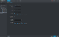
Door Config in DSS Express

Card Reader:Wiegand
| Port | Cable Color | Cable Name | Description | |
|---|---|---|---|---|
| CON1 | ||||
| White | 35px | D1 | Wiegand D1 input (connected to external card reader)/output (connected to controller). | |
| Green | 35px | D0 | Wiegand D0 input (connected to external card reader)/output (connected to controller). | |